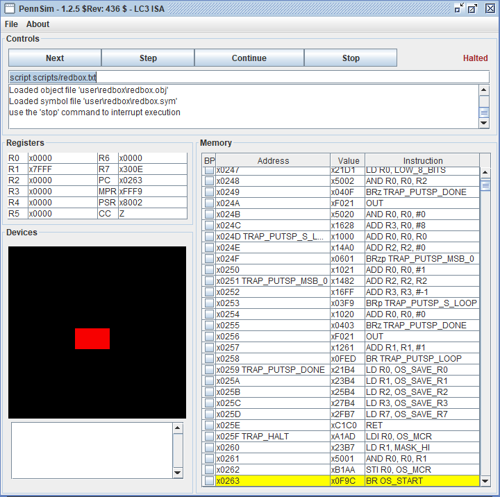
C.1. Draw Red Box
This example makes use of the graphics display, memory operations, and flow control. Please review these topics as needed while going through this example.
Example
Usage
The example and along with the simulator can be found in this repository. The scripts/redbox.txt file contains the commands needed to run the program. You can run the script directly with the script command from the simulator using script scripts/redbox.txt.

Walkthrough
When drawing on the graphics display, you need to decide the image’s position, its size, and its contents. You pick a point to reference the image too and then draw around that point. In the case of the red box, its top left corner is used. The rectangle’s size is its width and height. Its width is determined by how many pixels are in a row and its height how many pixels are in a column. The content of the image is just the color red, but we could make it more complex, such as a pig with a transparent background.
The values used to determine these dimensions are stored in memory using .FILL on lines 29-33. We have the following values listed below:
GD_STARTset toxDDB0is the pixel location of the top left corner of the rectangle. Remember that the graphics display is controled with memory locationsxC000toxFDFF.COLOR_REDset tox7C00is the 15-bit color value for red. The MSb is not used by the computer.HEIGHTandWIDTHset to#15and#25are the number of pixels for the sides of the rectangle.ROW_OFFSETset to#103is needed to move from one row to the other and is discussed later.
The logic for drawing the image does not change from image to image, but we can change these stored values to alter our image. We can tweak the position, size, and color of our rectangle by adjusting these values.
Set Up Position Pointer
First, let’s look at the code, STR R1, R0, #0, on line 16. To change the color of the pixel, the color value must be stored in the memory location representing that pixel. With the STR opcode, we use R1 to hold the color value and R0 to hold the address of the memory location we want to store to. They are initialized on lines 8 and 9. In terms of the computer, STR R1, R0, #0 stores the value of R1, the color value, in the location specified by the address in R0. Functionally, this snippet of code turns the pixel at the location specified in R0 to the color red.
Note that the offset is always set to #0. We cannot change the offset dynamically, while the code is running, and so we must change R0. R0 will cycle through each location of each pixel of the rectangle starting with xDDB0 as loaded on line 8.
Inner Loop Paints a Row
The first pixel is painted and then in each iteration of the inner loop, R0 is incremented by #1 so that the next loop iteration will paint the pixel immediately to the right red. For however many times the inner loop executes, that is how many pixels are turned red from left to right. If we were to add #-1, or decrement R0, then we would be turning pixels red from right to left. Thus the inner loop creates a row.
The inner loop consist of lines 15-19. Before the inner loop executes R3 is given the WIDTH which is #25 and is implemented as the counter. Each iteration of the loop, the pixel is turned red, the position pointer is moved to the right, and the counter is decremented. The counter is then checked on line 19. If the counter has made it to zero or is negative then we have printed a complete row and the loop is broken.
The Row Offset
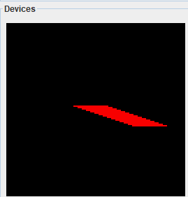
The row offset moves us from the last pixel in a row, to the start of the first pixel on the next row. Each row is 128 pixels wide. Each row of the rectangle starts on pixel 48. We move 25 pixels to the right and the row ends at pixel 73. The goal is to setup the position pointer to pixel 48 on the next row. The pixels roll over at 128. So we need to increment R0 by 55 to get to the start of the next row. Then we need to go 48 more pixels to get to the start of the rectangle. In all, we must add 103 pixels to the end of the current row to get to the start of the next row. This value turns out to be just 128 minus the width of the rectangle, 128 - 25 = 103. If you change the width of the rectange you must recalculate and update this value, or program it in to change dynamically. Otherwise, the image will be skewed.

The Outer Loop Gives Height
If the inner loop only runs one time, only one row gets printed. If you comment out lines 21-25, only one row is printed to the graphics display. The outer loop consist of lines 13, 14, and 20-25. The outer loop sets up the counter for the inner loop, executes the entire inner loop, then checks its own counter and adds the row offset. The inner loop iterates the pixels to draw a row, the outer loop iterates the rows to draw the rectangle.
The outer loop provides the second dimension of height to the rectangles size. This is loaded into R2 on line 10. Within each iteration, first the counter is setup for the inner loop in R3. The inner loop executes and draws the row. On line 20, the outer loop counter is decremented. If its zero or negative then the outer loop exits and the rectangle is drawn. If there are more rows to be drawn, then the row offset is applied to the position pointer and the outer loop iterates.
Summary
Important values that cannot be coded into the opcode are setup as stored values to be loaded in lines 29-33.
In lines 8-10, the program sets up the location to start drawing pixels along with the color value and sets up the outer loop counter which is the rectangles height.
Then in lines 13 to 25 the rectangle is drawn pixel by pixel and row by row. Each iterations of the inner loop draws a pixel until a row is completed. After a row is finished, the position counter is moved to the next row. This is the outer loop, and this happens for each row until all rows are printed.
When every pixel of every row and every row is printed, then the rectangle is complete and the program is done.